There are three main frequencies that common RFID tags operate on: low frequency (LF), high frequency (HF), and ultra-high frequency (UHF). These three are mutually exclusive, so we needed to determine where to start. We enumerated some of the commonly-found tags we’d like to scan:
- Passports 13.56 mHz HF ISO 14443 Type A
- Parking passes 865~928 mHz UHF ISO 18000-6C
- Dog/cat/pet implants 125 kHz LF ISO 11784 & 11785
- Key fobs 125 kHz LF
- Mcard 13.56 mHz HF Mifare DESFire EV1 ISO 14443-4 Type A Smart Card
- Library books 13.56 mHz HF ISO 14443A
- Library books 13.56 mHz HF ISO 15693
- Library books 860~960 mHz UHF EPCglobal
- Credit cards/Payment cards 13.56 mHz HF
- Flocktag 13.56 mHz HF MiFare Classic 1K ISO/IEC 14443 Type A
Of all the RFID tags we wanted to skim, it seemed that HF was the most popular. Luckily, I was able to borrow a Samsung Galaxy Nexus running Android 4.3 Jelly Bean that had this exact reader built into it. The Galaxy Nexus uses Near Field Communication (NFC) on the same frequency that we want to scan, 13.56 mHz. Using the built-in reader and the NFC TagInfo app from NFC Research Lab Hagenberg, we were able to scan, parse, and save the data from a U.S. passport, the U-M school ID card, a FlockTag Rewards card, and a MasterCard® PayPass™.
This was a good start, but we needed to extend the antenna, in order to hide it in our couch. While there are expensive solutions available online, I decided to try a similar approach to what these folks did. I was pleasantly surprised when it worked on the first try!


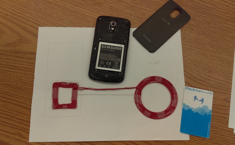
We learned that the NFC antenna in the phone is actually in the battery. In fact, the Galaxy Nexus won’t scan any RFID when I put a counterfeit battery in it. However, when we use the correct battery, we can get the phone’s antenna to pair with an external antenna just by mimicking the size and shape of the former and setting them next to each other.
*Technical point: As confirmed by antenna-theory.com, an “NFC antenna isn’t an antenna at all – it is really just a [magnetic] inductor.”
So, the square part of our antenna must be that specific size and shape for this phone, but the circular part and the distance between them can be adjusted. We will be experimenting with different diameters and distances. Once we find a good combination, I’ll be able to hide the antenna in our RFID couch.
Check out this 30-second video of our DIY RFID antenna in action!
The antenna was made using UL1007 standard hook-up wire, 300V. We used about 10.5ft of wire to wrap the coils, and then soldered the ends together to made it all one big loop. Here is a link to the PDF with the design shown in the video above.
